Networking Details
AWS Vanilla K8s Cluster Deployment (Self-Managed)
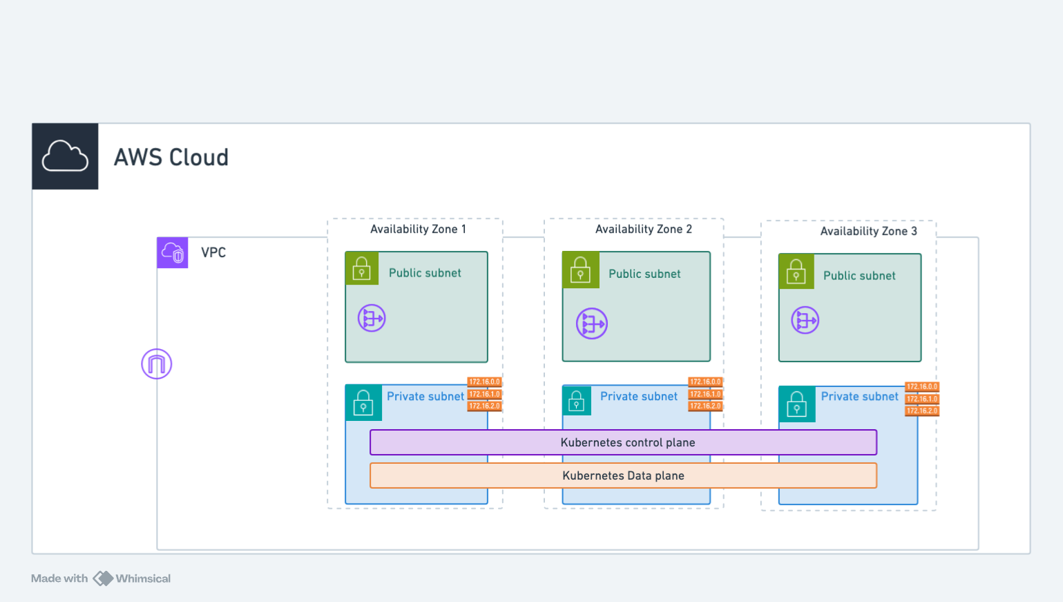
The architecture diagram above illustrates the networking setup for AWS Self-Managed Kubernetes (K8s) clusters. Whenever an Application Load Balancer (ALB) or Network Load Balancer (NLB) is created, it is provisioned in the public subnets. For the K8s API Server is backed by a Network Load Balancer (NLB) and the control plane is deployed in a private subnet. The worker nodes are deployed in private subnets and joined to the control plane using the private IP address of the nodes.
For example, in the us-west-2 region cluster deployed in us-west-2a, us-west-2b, and us-west-2c availability zones:
- Control plane: One node group per availability zone (us-west-2a, us-west-2b, us-west-2c)
- Worker nodes: One node group spanning all availability zones
NAME				        ROLE		    MACHINETYPE	MIN	MAX	SUBNETS
control-plane-foo-cluster-0	ControlPlane	t3.medium	1	1	us-west-2a
control-plane-foo-cluster-1	ControlPlane	t3.medium	1	1	us-west-2b
control-plane-foo-cluster-2	ControlPlane	t3.medium	1	1	us-west-2c
worker-test-mg-ng-0		    Node		    t3.medium	1	1	us-west-2a,us-west-2b,us-west-2c
GCP Vanilla K8s Cluster Deployment (Self-Managed)
The GCP self-managed Kubernetes cluster uses a similar architecture to AWS, with control plane and worker nodes deployed in a VPC network.
┌─────────────────────────────────────────────────────────────────────┐
│  GCP Project                                                        │
│  ┌───────────────────────────────────────────────────────────────┐  │
│  │  VPC Network                                                  │  │
│  │                                                               │  │
│  │  ┌─────────────────────────────────────────────────────────┐  │  │
│  │  │  Regional Subnet (spans all zones)                      │  │  │
│  │  │                                                         │  │  │
│  │  │  ┌───────────────┬───────────────┬───────────────┐      │  │  │
│  │  │  │  zone-a       │  zone-b       │  zone-c       │      │  │  │
│  │  │  │ ┌───────────┐ │ ┌───────────┐ │ ┌───────────┐ │      │  │  │
│  │  │  │ │ CtrlPlane │ │ │CtrlPlane  │ │ │ CtrlPlane │ │      │  │  │
│  │  │  │ └───────────┘ │ └───────────┘ │ └───────────┘ │      │  │  │
│  │  │  │ ┌───────────┐ │ ┌───────────┐ │ ┌───────────┐ │      │  │  │
│  │  │  │ │  Workers  │ │ │  Workers  │ │ │  Workers  │ │      │  │  │
│  │  │  │ └───────────┘ │ └───────────┘ │ └───────────┘ │      │  │  │
│  │  │  └───────────────┴───────────────┴───────────────┘      │  │  │
│  │  └─────────────────────────────────────────────────────────┘  │  │
│  │                                                               │  │
│  │  ┌─────────────────────────────────────────────────────────┐  │  │
│  │  │  Cloud NAT ────► Internet Gateway                       │  │  │
│  │  └─────────────────────────────────────────────────────────┘  │  │
│  │                                                               │  │
│  │  ┌─────────────────────────────────────────────────────────┐  │  │
│  │  │  External Load Balancer (K8s API Server)                │  │  │
│  │  └─────────────────────────────────────────────────────────┘  │  │
│  └───────────────────────────────────────────────────────────────┘  │
└─────────────────────────────────────────────────────────────────────┘
The architecture uses:
- Regional subnet: Single subnet spanning all availability zones (unlike AWS per-zone subnets)
- Control plane nodes: One per availability zone for high availability (3 nodes minimum)
- Worker nodes: Distributed across availability zones
- Cloud NAT: Provides outbound internet access for private instances
- External Load Balancer: Exposes the Kubernetes API server
For example, in the us-central1 region cluster deployed across us-central1-a, us-central1-b, and us-central1-c zones:
- Control plane: One node per zone for high availability
- Worker nodes: Distributed across all zones
NAME                              ROLE          MACHINETYPE    MIN  MAX  ZONES
control-plane-foo-cluster-0       ControlPlane  n2-standard-2  1    1    us-central1-a
control-plane-foo-cluster-1       ControlPlane  n2-standard-2  1    1    us-central1-b
control-plane-foo-cluster-2       ControlPlane  n2-standard-2  1    1    us-central1-c
worker-foo-cluster-ng-0           Node          n2-standard-4  1    3    us-central1-a,us-central1-b,us-central1-c
Key Differences: AWS vs GCP Self-Hosted Networking
| Feature | AWS Self-Hosted | GCP Self-Hosted |
|---|---|---|
| Subnet Model | Per-zone (public + private) | Regional (spans all zones) |
| NAT | NAT Gateway per AZ | Cloud NAT (regional) |
| Load Balancer | NLB for K8s API | External TCP LB |
| VPC ID | vpc-xxxx format | Network name (e.g., my-vpc) |
For more information on GCP networking, see the Google Cloud VPC documentation.